|
To enter data for an RBD element |

|

|
|
|
To enter data for an RBD element |
|
|
To enter data for an RBD element
|
To enter data for an RBD element |
|
|
|
|
To enter data for an RBD element |
|
|
Do one of the following:
| • | From the Item menu, choose Edit. In the Element Parameters Definition dialog box, enter the element’s specifications. Choose OK. |
or
| • | Activate the Product tree view. Drag and drop a tree item into the RBD element; RAM Commander displays the reliability data. |
RAM Commander updates the reliability block diagram.
The Element parameters definition dialog box contains several fields, as shown below:
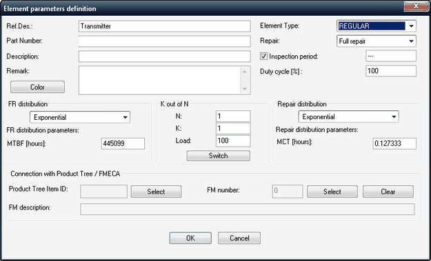
When you add elements to the RBD, you must specify their characteristics in the Element parameters definition dialog box’s fields. These characteristics include:
FR distribution |
A probability density function describing the part’s failure rate. |
FR distribution parameters |
Parameters describing the FR distribution, such as μ and σ for the Normal distribution or MTBF for exponential distribution. |
K-out-of-n |
K—the minimum number of units that must operate for the element to function N—the total number of units in the element Load defines the status of non-functional elements: Load = 0 - Element non-operating - standby redundancy 0 < Load < 100 - Element partially stressed warm redundancy Load = 100 - Element with active redundancy |
Repair |
Specifies the repair policy for failed elements. If you select Restricted or Full repair, you must specify the distribution for the repair time as for the FR distribution. Without repair - Element is not repaired upon failure. (The repair distribution parameters are ignored.) Restricted repair - Only one element is repaired at a time (queuing for repair). Full repair - Any number of elements can be simultaneously repaired (no queuing). |
Inspection period |
Applicable for Monte Carlo simulations only and if the element has either Restricted or Full repair. Inspection Period check box not checked - Element sent to repair upon RBD failure. Inspection Period check box checked and value = 0 - Element sent to repair upon component failure (default). Inspection Period check box checked and value > 0 - Element checked every [Inspection Period] hours. If failed, sent to repair. |
Duty cycle |
Amount of time the part is operational relative to mission time. |
ID |
Taken from the product tree; used for updating element data from the product tree. |
FM Number |
Taken from the FMECA analysis; used for updating element data from FMECA. |
Description |
For descriptive purposes only. |
Part number |
Taken from tree data; for descriptive purposes only. |
Ref. Des. |
Reference designator - element name. Taken from product tree data. If multiple elements have the same Reference designator, "Identical" calculation and simulation recognizes them as identical and then assumes that it is a single equipment block even if it appears in multiple places in the RBD. |
Remark |
For descriptive purposes only. |