|
FTA basics |

|

|
|
|
FTA basics |
|
|
FTA basics
|
FTA basics |
|
|
|
|
FTA basics |
|
|
Fault Trees are one of the most widely used methods in system reliability and failure probability analysis. A Fault Tree is a graphical representation of events in a hierarchical, tree-like structure. It is used to determine various combinations of hardware, software, and human error failures that could result in a specified risk or system failure. System failures are often referred to as top events. A deductive analysis using a Fault Tree begins with a general conclusion or hazard, which is displayed at the top of a hierarchical tree. This deductive analysis is the final event in a sequence of events for which the Fault Tree is used to determine if a failure will occur or, alternatively, can be used to stop the failure from occurring. The remainder of the Fault Tree represents parallel and sequential events that potentially could cause the conclusion or hazard to occur and the probability of this conclusion.
A fault tree is a graphical representation of a logical structure representing undesired events ("failures") and their causes. You create the logical structure by using gates and represent undesired events by using basic events. Reliability parameters are assigned to the basic events. Widely used in system reliability studies, fault tree analysis offers the ability to focus on an event of importance, such as a highly critical safety issue, and work to minimize its occurrence or consequence. The probability of the top-level event can then be determined by using mathematical techniques. The resulting fault tree diagram is a graphical representation of the chain of events in your system or process, built using events and logical gate configurations.
The main purpose of Fault Tree Analysis is to evaluate the probability of the top event using state-of-the-art analytical and/or statistical methods. These calculations involve system quantitative reliability and maintainability data, such as failure probability, failure rate, expected failure, down time, repair rate, etc.
Two types of analysis can be conducted using Fault Trees:
| • | Qualitative Analysis: performed by means of Minimal Cut Sets (MCS) building |
| • | Quantitative Analysis: calculating the Absolute probabilities, i.e. the probabilities of system failures |
Definition: A Cut Set is a collection of basic events that if all its events occur, the fault trees top event is guaranteed to occur.
A Minimal Cut Set is such Cut Set that, if any basic event is removed from the set, the remaining events collectively are no longer a cut set. A cut set that includes some other sets is not a minimal cut set.
For large trees, with a large number of identical events, the number of MCS may be very large increasing the calculation time immensely. In this case, MCS Cut-off is used. During the Cut-Off, some minimal cut sets, which barely affect the final result, can be deleted. Three Cut-Off parameters are the Max. MCS number for Cut-Off, Relative cut-off value and Relative Cut-Off order (see Building FTA diagrams, Define FTA properties paragraph). When the MCS count in calculated tree increases the Max. MCS number, the Cut Off process is performed. If the relative affect on the calculation result for the MCS is less than the Relative cut-off value, the MCS is deleted.
The following FTA elements are used and supported in the RAM Commander software:
|
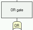
OR gate - output event occurs if any of the input events occurs. |
|
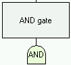
AND gate - output event occurs only when all the input events occurs simultaneously. |
|
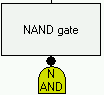
NAND gate – NOT AND operation |
|
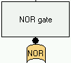
NOR gate – NOT OR operation |
|
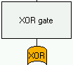
XOR gate – Exclusive OR operation |
|
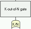
K-out-of-N gate - output event occurs if K or more of the input events occurs |
|
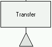
Transfer gate – transfer to another tree (sub-tree) |
|
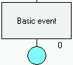
Basic event - represents a basic equipment fault or failure that requires no further development into more basic faults or failures. |
|
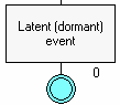
Latent (Dormant) event - similar to basic events but indicates the latent failure which is discovered by periodical tests. |
|
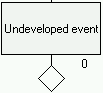
Undeveloped event - represents a fault event that is not examined further because information is unavailable or because its consequence is insignificant. |
|
House event – represents a condition or an event which is TRUE (ON) or FALSE (OFF) (false). |
|
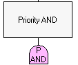
Priority AND gate - output event occurs only when all the input events occurs in the specified order. |
Notes:
| • | In addition, NOT operation can be performed on gates and events. |
| • | A diagram may contain unlimited number of free-positioned remark boxes with descriptive text and pictures. |
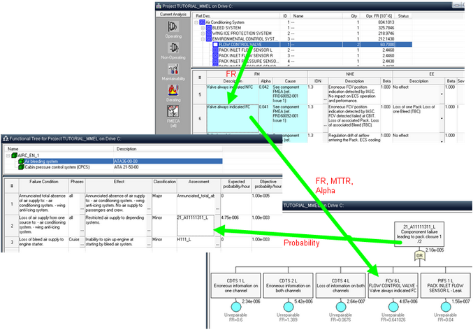
FTA module is integrated with other RAM Commander modules - Reliability, FMECA and Safety. The picture below illustrates linkage between Product tree, FMECA, FTA and Safety (FHA) modules - FTA uses Reliability and FMECA data for basic events probabilities calculation, Safety module in turn uses FTA for failure probability calculation: