|
FTA diagram building |

|

|
|
|
FTA diagram building |
|
|
FTA diagram building
|
FTA diagram building |
|
|
|
|
FTA diagram building |
|
|
When a new diagram is opened, the tree top event is created. You can now start the tree building by adding successors (child items) to the top event.
To add a successor (child) to the tree element:
| 1. | Select the tree element and then right-click. Choose Add Element from the pop-up menu. |
or
Select the tree element and press the F7 key.
The FTA element data screen is displayed.
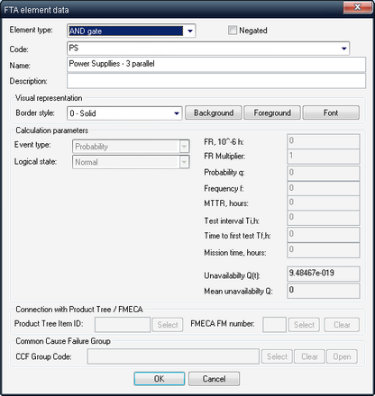
| 2. | Select FTA Gate/Event type. Relevant fields on the data screen will be enabled. |
| 3. | Specify gate/event code, name and description. For Event (basic, undeveloped or house) specify event probability calculation type and parameters. See the list of parameters in the table below: |
Field |
Field description |
|---|---|
Code |
Enter the element code in this text box. This should be unique for the diagram. Events with the same code are considered as identical during the calculation. For a gate, enter its code. For an event, enter the code for the new event or choose it from the list, if the event is already in the library. New node automatically receives the Code equal to the predecessor’s node code plus the number of successors. For example, if top event’s code is “AAA”, the predecessors receive codes “AAA-1”, “AAA-2”, etc. This is only a default value and can be changed by user. |
Name |
Enter the element name in this text box. |
Description |
Enter a description for the element in this text box. |
Negated |
Select this check box if you want the gate or event to be negated (NOT operation applied). |
K |
Enter a value for K-out-of-N gate - K argument. |
N |
Enter a value for the N for K-out-of-N gate (calculated automatically by the number of gate's children) |
Border style |
Select a border style of the gate/event box (Solid, Dot, etc.) from the drop down list. |
Background color |
Select a background color of the element from the color palette. |
Font |
Select a font for the element code and name. |
Foreground color |
Select a foreground color of the element from the color palette. |
Event type |
Select an Event reliability model from the list (Probability, Frequency, Repaired, Unrepaired, etc.). See the detailed description of available models in the Basic Event Types paragraph. |
Logical state |
Select a Logical state for House events from the drop-down list. |
FR |
Select a Failure rate from the drop-down list (failures per million or billion of hours, depending on project settings). |
FR multiplier |
Enter a value for Failure Rate multiplier. (FR used in unavailability calculation is item FR * FR Multiplier.) |
Probability q |
Enter a value for Probability q. |
Frequency f |
Enter a value for Frequency F. |
MTTR |
Enter a value in hours for MTTR (Mean Time To Repair). |
Test interval |
Enter a value in hours for the Test interval (time between periodical tests). |
Time to first test |
Enter a value in hours for Time to first test. |
Mission time |
Enter a value in hours for the Mission time. |
Q(t) |
Calculated value for the Unavailability Q(t) - probability of failure at a given time point. |
Q mean |
Calculated value for the Probability or long-term steady-state average unavailability, Q. |
Tree ID |
For events, ID of linked element in Product Tree. Press the "Select" button next to the field to pick up product tree item from the product tree. |
FM number |
For events, number of FMECA Failure Mode of linked element in Product Tree. Press the "Select" button next to the field to pick up specific failure mode from the list of linked product tree item's failure modes. |
CCF Group |
Code of Common Cause Failure Group the basic event belongs to. Use "Select" and "Clear" buttons near this field to add/remove it from the CCF Group. |
| 4. | Press Ok. Newly created event or gate will appear on the diagram. |
To edit tree element, double-click on it, or right–click on it and choose Edit from the pop-up menu. Data screen described above is displayed.